Build a Laser Diode LiFi Link with a Holographic Diffuser
By Breadboardhub Staff · Published 2026-08-12
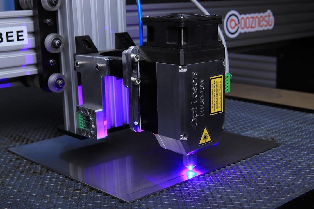
Photo by Opt Lasers on Unsplash
A 500 mW laser diode, a holographic diffuser, and a photodiode receiver can move data through the air at nearly 1 Gb/s across a room, no RF spectrum license required. Here is how the hardware fits together and where the real design constraints live.
The Basic Architecture
A LiFi link built around a laser diode (LD) instead of an LED gets you roughly 10x more usable modulation bandwidth. A typical high-power LD like the ones used in projector or fiber-pump modules in the 650-850 nm range can be intensity-modulated (switched on and off, or analog-amplitude-varied) up to several hundred MHz. Compare that to a phosphor LED, which rolls off somewhere around 20-30 MHz unless you do blue-filter tricks.
The transmitter chain has three pieces:
- Laser diode driver. You need a bias-T or a dedicated LD driver IC (Analog Devices ADN2530, iC-Haus iC-WJ, or a discrete bias-T built from a 100 nH RF choke and a DC blocking capacitor, 100 pF is a starting point) to combine a DC bias current above threshold with your modulation signal. Keep PCB traces short. At 250 MHz a centimeter of unmatched trace is a problem.
- Holographic diffuser. A raw laser beam is dangerous and covers a spot, not a room. A holographic diffuser (Edmund Optics, Thorlabs, or LightShaper stock them in 10, 20, 30, 60 degree cone angles) scatters the beam into a controlled cone while preserving most of the optical power. A 20-degree diffuser on a ceiling at 2.5 m height illuminates a circle roughly 0.9 m in radius at desk height. Scale up: at the same ceiling height a 60-degree diffuser covers about 2.7 m radius but the power per unit area drops as the cone widens, so link margin shrinks. The modeling work behind this article shows a 20-degree diffuser covers a 4.2 m radius cell from a standard ceiling mount, which comfortably covers one room.
- IM/DD receiver. Intensity modulation, direct detection. A silicon PIN photodiode (Hamamatsu S5971, Vishay TEMD5110, or similar) feeds a transimpedance amplifier (TIA). The TIA converts photocurrent to voltage. An OPA657 or THS3201 work well at bandwidths into the hundreds of MHz if you keep the photodiode capacitance low, pick a small-area die. The gain-bandwidth product of the TIA sets your ceiling: a 1 GHz GBW op-amp with 1 kOhm feedback gives you roughly 1 MHz bandwidth, which is useless here. You want a wideband TIA IC like the MAX3665 or a discrete design targeting 250 MHz+ bandwidth with feedback resistance in the range of 50-200 ohms and a careful layout.
The Bottleneck Nobody Talks About
Many published LD LiFi demos report speeds of 1-2 Mb/s and then claim that is the optical link limit. It almost never is. The laser and photodiode are capable of hundreds of Mb/s. What is actually limited is the UART or SPI interface connecting a microcontroller to the driver circuit. A UART running at 115200 baud gives you 115.2 kb/s. Even a fast UART tops out at 1-2 Mb/s. The optical front end is sitting idle while the serial interface is the choke point. If you want to measure true optical bandwidth, bypass the MCU serial port entirely. Feed a signal generator directly into your bias-T and use a fast oscilloscope or spectrum analyzer to measure the 3 dB electrical bandwidth of the link.
The modeling work validated in the paper referenced below shows that the same optical hardware bottlenecked at 2 Mb/s by a UART is capable of 930 Mb/s with 16-QAM modulation at 14 m range, and 1.86 Gb/s at 5 m with 256-QAM, when driven at the actual 250 MHz electrical bandwidth.
Noise Sources to Model and Measure
Three noise sources dominate:
- Shot noise from ambient light hitting the photodiode. Point a photodiode at a fluorescent or LED ceiling light and you are injecting a large photocurrent whose shot noise raises your noise floor. An optical bandpass filter (narrow passband centered on your laser wavelength, 10 nm bandwidth is typical) cuts most of this.
- Thermal noise in the TIA feedback resistor. Lower resistance means more bandwidth but less transimpedance gain, so you need more optical power to keep SNR up. This is the fundamental gain-bandwidth trade-off in direct detection receivers.
- Relative intensity noise (RIN) from the laser itself. Single-mode laser diodes have lower RIN than multimode ones. At high modulation depths RIN can become the dominant floor. Keep your LD well above threshold, the RIN drops sharply once you are 20-30% above threshold current.
Modulation and Link Budget
For a simple proof of concept, OOK (on-off keying) is easiest: the laser is on for a 1 bit, off for a 0. The modeling shows OOK at this power level works out to about 23 m maximum range before the BER becomes unmanageable. For higher throughput, move to M-QAM on a subcarrier (OFDM-style multicarrier or single-carrier with equalization). 16-QAM needs roughly 4 dB more SNR than OOK for the same BER, but quadruples your bits per symbol. A forward error correction (FEC) scheme with a threshold around 3.8e-3 raw BER (standard hard-decision FEC) gives you margin to work with.
Simulation Before You Solder
The open-source ns-3 module and Python link-level simulator published alongside the paper (see citation below for the arXiv link and the associated code release) let you plug in your actual hardware numbers: transmit power, diffuser angle, photodiode area and responsivity, TIA noise figure, and modulation order. You can sweep range and beamwidth to find the trade-off before you spend money on optics. The Python Monte Carlo validator runs BER curves you can compare against your own measurements once hardware is on the bench.
Honest Limitations on a Hobbyist Bench
A breadboard is a hostile environment for this kind of work. Parasitic capacitance from jumper wires and solder blobs kills bandwidth above a few MHz. You need a proper PCB with a continuous ground plane, 50-ohm controlled impedance traces to the laser driver and TIA, and SMD components. A digital oscilloscope with at least 500 MHz bandwidth (and ideally 1 GHz+) is necessary to see the signal integrity problems. Measuring BER properly requires a BERT (bit error rate tester) or a sufficiently fast logic analyzer. Eye diagrams at 250 MHz need a real-time or sampling oscilloscope. This is not a one-weekend project on a solderless breadboard, but the optical and electrical concepts are fully understandable at the hobbyist level, and a lower-speed version using an LED driver and a slow photodiode is a genuine first step.
For the full system model, validated simulations, and all underlying equations, see "Laser-Diode LiFi With Diffused-Beam Optics: System-Level Modeling and a Cross-Validated ns-3 Simulation Framework" by Hussain Ahmad, Syed Muhammad Talha Gillani, Toheed Omer, and Saleem Aslam, available at arxiv.org.
Attribution
Adapted from “Laser-Diode LiFi With Diffused-Beam Optics: System-Level Modeling and a Cross-Validated ns-3 Simulation Framework” by Hussain Ahmad, Syed Muhammad Talha Gillani, Toheed Omer, Saleem Aslam, licensed under CC BY 4.0 (https://creativecommons.org/licenses/by/4.0/). Source: https://arxiv.org/abs/2608.10950.
Original arXiv papers: